Beetle Bros. Home Robot Arena 2 BBEANS
Arthrobotics Downloads Rules
Vanitas Tutorials Standings
Hall of Fame
Ironbot

How to Mod RA2 Without 3D Studio Max

The .TXT File

Making/Editing .TXT Files

Troubleshooting

The .GMF File

Reskinning Components

Making and Editing Attachment Points

Editing the Mesh

Troubleshooting

The .TXT File

The first step in making custom components for RA2 is understanding the .txt files for the components. These files are placed in the 'Components' folder (or the main 'Robot Arena 2' folder if they are compressed into a .cfz file) and are just a collection of parameters used to determine how they behave in the game. Stuff like mass, power, durability, and name.

Editing .txt files is very simple and also quite powerful, perfect for beginners. All you need to do it is some text-editing program like Notepad or Wordpad. A CFZ compiler/decompiler is optional if you want to access the .txt files for the stock components. To edit .txt files, simply open them in your text-editing program, change a few things, and save it. It's that easy! But in order to do it right, you need to know what all the parameters do. Here is a list of all the .txt file parameters you are likely to find. A lot of this information comes from http://www.robotarena.com/exporter/comp_file_format.htm.

Basic stuff: These parameters must be present in every component's .txt file.

  • name = x The name for the component that will be displayed when you click on it in the bot lab.
  • dir = x The name of the folder where the .gmf file and preview picture for the component are.
  • model = x The name of the .gmf file (3D model) used for the component.
  • preview = x The name of the .bmp file used as a preview picture in the bot lab. It will usually be something like 'component_preview.bmp'.
  • type = x What section of the components list this component goes under: 'power', 'extenders', 'mechanics', 'mobility', 'weapons', or 'extras'.
  • base = x What type of component this is: 'AirTank', 'AxleMount', 'Battery', 'BurstMotor', 'BurstPiston', 'Cannon', 'Chassis' (not normally used), 'Component' (used for anything with no function such as armor plates), 'ControlBoard', 'Flamethrower', 'Hovercraft', 'Magnet', 'ServoMotor', 'ServoPiston', 'SpinMotor', 'Weapon' (used for any kind of spike, hammer, etc.), 'Wheel'.
  • styles = x The names of the components and .txt files to be in a drop-down list in this component's slot. The format is: (name of this component), style1.txt, (name of first style component/second component on list), style2.txt, (name of second style component/third component on list) and so on. The .txt files can be called anything. If you don't want any style options, set style = Default.
  • description = x The description for the component that will be displayed in the bot lab.

Advanced stuff: These parameters are optional and can go in any component's .txt file.

  • hitpoints = x How much damage this component can take before breaking.
  • fracture = x The minimum amount of damage this component must take (in a single hit) after it has 0 hitpoints in order to break off.
  • material = metal(x) The material of this component (metal) and the amount of damage it does (x). You can also set material = rubber(x) or arenium(x) but it will not do damage. Rubber components will not take damage from hitting the walls and floor.
  • mass = x How heavy this component is. Changing the mass will only change the mass of the master object, not any sub-objects. It can be any number, even negative.
  • hidden = x Whether or not the player can see this component. hidden = 0 means it can be seen in the bot lab, hidden = 1 means it can't, and hidden = 2 means you must type cheatbot2 to see it.
  • standard = x Whether or not this component is standard or cheat. standard = 0 means it is a cheat component (and can't be used in multiplayer) and standard = 1 means it is a stock component.
  • passthru = x Name(s) of the parts of the component that can pass through the chassis. If the part has a geometry proxy (collision mesh), the name of that must be used.
  • alwaysvisible = true Whether or not this component is visible when it is attached directly to the chassis. It is set to false by default.
  • sort = x Number that determines where this component will be on the list. It can be any whole number (negative infinity to positive infinity). Smaller numbers go first on the list and large ones go last. If there is a tie in sort numbers, order goes alphabetical.
  • master = x The name of the main body of the component in the .gmf file. All the connection points and sub-objects will be oriented towards the master.
  • attaching = x The name of the body in the .gmf that parts will be attached to.
  • attachsound = sounds\x.wav The sound it plays when this component is attached. Usually cmp_generic.wav.
  • damagesounds = sounds\x.wav The sound it plays when this component takes or deals damage.
  • damageable = false This doesn't seem to do anything, but maybe it does. Set to true by default.

Weapon stuff: These parameters are optional and are only used for weapons.

  • piercing = x How much piercing damage this component does.
  • concussion = x How much concussion damage this component does.
  • normal = w x y z x y z The directions in which this component can do damage. If w is 0, the component can only do damage in one direction; if it is 1, it can do damage either way. x, y, and z determine the 'sharp edge' of the component (the direction it can do damage). The sharp edge will face towards a point with the coordinates (x, y, z) (so for example, if you want the component to do damage in only the +x direction, xyz would be (1, 0, 0)). The second x, y, and z are optional in case you want two 'sharp edges'.
  • decal = nameofdecal.tga x y z sx sy t The graphic (scratches, etc.) the weapon applies to the opponent's chassis. x, y, and z determine direction again. sx and sy determine how big the decal is (1 is full size). t determines the type (0 for alpha, 1 for additive, not sure exactly what these are). The .tga files for the decals are stored in the Arenas folder.

Motor stuff: These parameters are optional (if you don't specify them defaults will be used) and are only used for motors.

  • power = x y How powerful this motor is. x is the maximum speed and y is the gain (something like torque). For burst motors, this is how powerful the motor is when it is winding back up. For car steering units and hovercraft engines, there is only one number for power which combines speed and gain.
  • burst = x y z For burst motors only. x is the initial force the motor fires with, y is the maximum speed it can reach, and z is the gain.
  • elecMaxInOutRate = -x Amount of electricity this motor uses.
  • motorsound = sounds\x.wav For spin motors and servo motors only. The sound it plays when this motor is running.
  • firesound = sounds\x.wav For burst motors, pistons, cannons, flamethrowers, and magnets only. The sound it plays when this motor fires.
  • runsequence = sounds\x.wav, sounds\y.wav, sounds\z.wav For servo motors and servo pistons only. The sounds it will play when this motor runs. x is for spinup, y is for running, and z is for spindown.
  • torque = x Amount of torque this motor spins with. Like gain, but will not dramatically increase the motor's speed. You need to set torque very high (several thousand) to have a noticeable effect.

Piston stuff: These parameters are required, but only for pistons.

  • power = x y Same for pistons as for motors: x is max speed, y is gain.
  • prismatic = bodyname, shaftname, x, y, z, v, w, t All the stuff for the piston. bodyname is the name of the main body in the .gmf and shaftname is the name of the sliding part in the .gmf. x, y, and z determine which way the piston fires. v is the starting position of the shaft and w is the ending position. t is the tensor scale. I'm not sure what it does, it can be left at 0 with no problems. The official site says it "sets attachment's inertia tensor to the base object's scaled by this amount; set to 0 to leave tensor unchanged".
  • airMaxInOutRate = x The amount of compressed air this piston uses.
  • force = x Like 'torque' for motors, except for pistons. Again, you need to set it to several thousand for any noticeable effect.

Power stuff: These parameters are required, but only for batteries and air tanks.

  • electotal = x The total amount of power this battery holds.
  • airtotal = x The total amount of compressed air this air tank holds.
  • elecmaxinoutrate = x The amount of current this battery supplies. Careful with the case! It's different than the one for motors.
  • airmaxinoutrate = x The amount of air flow this tank supplies. Careful with the case! It's different than the one for pistons.

Wheel stuff: These parameters are required, but only for wheels.

  • grip = x How much traction this wheel gets. A big number means more speed and control, a small number means less speed and more sliding around.
  • resistance = x Not sure exactly what this does, but it has something to do with turning. .2 is a good value.
  • contact = x The name of the wheel's traction zone in the .gmf file.

Making and Editing .TXT Files

Now that you know what all the parameters do, you're ready to make some components! Let's suppose you want to make a Hammer Head that is more powerful, lighter, and harder to break off than the stock one, can do damage in any direction, is a cheat component, and at the very end of the component list. First you would start with the basics: name, dir, model, preview, type, base, and description. Then you would add all the other stuff: piercing, concussion, hitpoints, fracture, damagesounds, decal, attachsound, standard, hidden, mass, and sort. You would also include no normal in the file. When it was all done, the .txt file for this component would look something like this:

Example .txt File

Go ahead and put that in your Components folder. You should now have an über-powerful hammer available at the end of your Weapons list whenever you type 'cheatbot2' as your bot name (assuming you have the 1.2 patch installed, if not set hidden = 0). Feel free to mess around with some of those parameters to see what they do, too!

One more example. Suppose you want to make a very tiny, very powerful, very light spin motor that drains very little electricity and that the game thinks is a standard component. For this, after doing the basics you might want to use the axle mount model and set its base to 'SpinMotor' instead of 'AxleMount'. Then just add power and sound parameters and you're good to go! The .txt file for this component would end up looking something like this:

Example .txt File #2

If you put that in your Components folder, you should have an axle mount that you can wire like a motor. It is weak on purpose; that's to get you to experiment with the settings yourself. Try upping the 'power' parameter a few notches for something more like what we originally had in mind. You also might adjust the mass to make this ultimate cheat motor even lighter. The possibilities are many with .txt file editing.

Troubleshooting

There are only a few things that can go wrong when you're just editing .txt files. If your game crashes when you click on your component, it could be for one of these reasons:

I have found that it is helpful to un-compress RA2.cfz using one of the aforementioned programs to see what the .txt files look like for all the components. Then I just copy them and change the parameters to make sure I don't make any mistakes.

The .GMF File

Now that you understand .txt files, it's time to tackle the heart of the component: the .gmf file. The .gmf file contains the 3D model used for the component, its attachment points, and a few game-related things. .gmf files that are compatible with RA2 can only be made with 3D Studio Max 4 or 5, which costs more money than the average person can afford just for making a few custom components. However, there is another way to make custom 3D models using only Notepad/Wordpad and a free program called Dummy's GMF Compiler, which you can get from here. This is much harder than .txt file editing, but much more powerful.

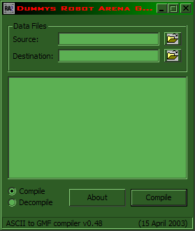
So how do you make custom .gmf's without 3D Studio Max? Well, you don't actually make them, but you can copy existing .gmf files and edit them in Notepad to make a new component. So how do you edit them? If you try to open a .gmf file in Notepad, it will just be unrecognizable, garbled characters. And if you try to save it, the file will become corrupted and any component that uses it will crash the game. That's where Dummy's GMF Compiler comes in. This tool will let you decompile .gmf files into recognizable words and numbers, then compile them back into the compressed form the game uses. When you run Dummy's GMF Compiler, it should look like this:

Before you can edit .gmf files, you need to decompile them, so check 'Decompile' at the bottom before doing anything else. Then click the folder by 'Source' at the top to select which .gmf file you want to edit. For this tutorial, we will be using the Ram Plate .gmf because of its simplicity, which is located in C:\Program Files\Infogrames\Robot Arena 2\Components\ram_plate\ramplate1.gmf. Enter this as the source .gmf. The destination can be anywhere. I usually have the destination be in C:\Program Files\Infogrames\GMFCompiler048 so the compiler is always close by, but it really doesn't matter. Now click 'Decompile' and you should find a readable .gmf file for the Ram Plate wherever you set your destination.

You might be a little overwhelmed when you first see what all is required just to make a simple ram plate. The file may be readable now, but it is still far from understandable. However, half of that stuff you will never need to bother with. As for the other half, here's a quick explanation of what it is. Anything I don't mention you don't need to know about.

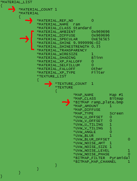
  • Materials: This section of the .gmf near the beginning determines how the component is skinned. A screenshot is shown below, with red arrows drawn by the important lines. The ones without red arrows you don't need to worry about.

    • MATERIAL_COUNT tells the computer how many different materials (or skins) there are in the file, in this case 1. You only need to change this number if you add or remove any materials, which you won't at this stage, so you can ignore it for now.
    • MATERIAL_CLASS is either Standard or Multi/Sub-Object. Multi/Sub-Object is used for applying multiple skins to the same object.
    • MATERIAL_REF_NO assigns a number to this material that is used later in the file to tell which part of the component gets which skin applied to it. With a single-part, single-skin component like the ram plate, you don't need to worry about this.
    • MATERIAL_AMBIENT, MATERIAL_DIFFUSE, and MATERIAL_SPECULAR tell what color the component is if it doesn't have a texture. The colors are in hexadecimal code (0xFFFFFF=white, 0x000000=black, 0xFF0000=red, and so on). This color only applies if there is no texture, so you would need to delete the TEXTURE in the ram plate .gmf in order to see it.
    • MATERIAL_SHINE and MATERIAL_SHINESTRENGTH determine how shiny and reflective this component is. 1 is super shiny, 0 is absolutely dull.
    • MATERIAL_TRANSPARENCY determines how transparent this component is. There will be no number here by default but you can add one if you want. 1 is invisible, 0 is completely solid.
    • TEXTURE_COUNT tells the computer how many different textures are in this material. You will very rarely need to deal with more than 1, so you can usually ignore this.
    • BITMAP determines what .bmp or .tga file to apply to this component. These skins are stored in the 'maps' folder in the folder containing the .gmf.
    • MAP_DIFFUSE determines what kind of map this is. It can be DIFFUSE (default), REFLECTION (shiny), OPACITY (semitransparent; black=transparent white=opaque), or SELFILLUM (self-illuminated).
    • MAP_TYPE determines how the texture is applied. It is usually Screen, but can also be Additive (appears brighter) and must be Spherical or Cylindrical for reflection maps. Note that Dummy's GMF Compiler cannot compile anything but DIFFUSE Screen skins, but if you're clever there is a way to modify the source code so it can.
    • BITMAP_FILTER determines how the texture is stretched or resized on the component. Pyramidal is basic and results in choppy pixels, while SAT blurs the edges for a smoother look.

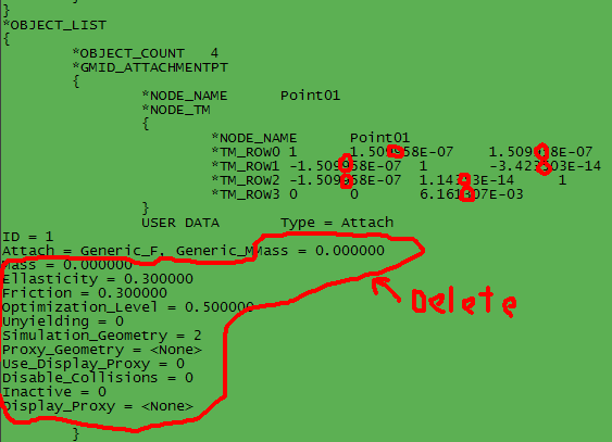
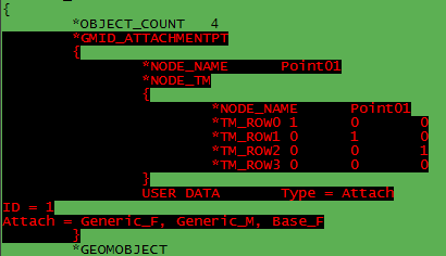
  • Attachment Points/object list: Attachment points are the green boxes where the component can be attached to things. They can go anywhere in the .gmf, so they can be hard to find sometimes. In the case of the ram plate, the attachment point is right after the materials. You will need to know what every line does if you are going to mess with them. The red lines in this picture are just to simplify things a bit: you can round any number in scientific notation with E-03 or smaller to 0 (which I have shown), and you can delete all that junk I circled. It's useless and I don't know how it gets in there.

    • OBJECT_COUNT tells the computer how many objects there are in this .gmf. It always comes right after the materials, not necessarily by an attachment point. It is important that you get this number right - if it is too big, the file won't compile; if it is too small, it will crash the game. Attachment points, mesh, hinges, and RBCollections count as objects.
    • NODE_NAME is just the name of the attachment point. It always goes Point01, Point02, etc. Note that there are two of them - you need to change both if you change one!
    • NODE_TM contains all the TM_ROWs (Transformation Matrix Rows) for the attachment points. TM_ROWs 0-2 determine what direction the attachment point faces, and TM_ROW3 is its x,y,z coordinates. I still don't understand how TM_ROWs 0-2 work, so when I want to change which way a connection point faces, I just copy them from another connection point. I do know, however, that multiplying TM_ROW1 and TM_ROW2 by -1 makes the point face in the exact opposite direction. I also know that the TM_ROWs for facing directly x, directly y, and directly z are: 100|010|001, 100|001|0-10, and 010|001|100.
    • ID is just the number in the NODE_NAME. The point with ID = 1 is the one that will be selected by default.
    • Attach = determines how this component can be attached. There are three types: Base, which includes the chassis, Axle, which includes motors and wheels, and Generic, which includes just about everything. They will be followed with _M or _F. M means components can be attached to this point, and F means this component can be attached to other stuff with this point. You can have as many of these values as you want.

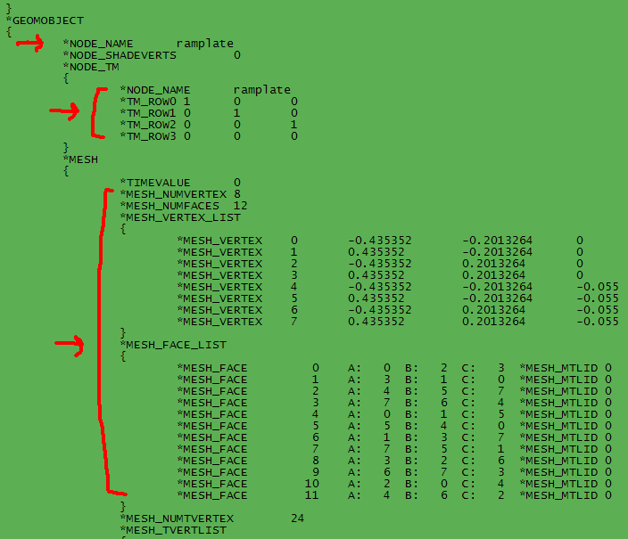
  • Mesh: This section of the .gmf contains all the meat: the actual 3D model. The mesh is a huge part of the file, but you really only need to bother with with the very beginning of it.

    • NODE_NAME is the name of this object. It will be used later in the RBCollection and possibly in the .txt file. Note that once again there are two of them. There are also some TM_ROWs here to determine what direction the mesh faces, but these ones get overridden by the ones in the RBCollection so they don't really matter.
    • MESH_NUMVERTEX and MESH_NUMFACES tell the computer how many vertexes and faces are in this mesh. You will most likely be leaving these numbers alone, but it's good to know what they do because they're important. I would NOT recommend attempting to add or remove vertexes or faces, because then you would have to mess around with the normals and TVERTs, which even I haven't figured out.
    • MESH_VERTEX is one of the 'corners' of the object. The layout is simple enough, the MESH_VERTEX is just followed by 4 numbers, the first of which is its number and the others are its x,y,z coordinates.
    • MESH_FACE is one of the 'sides' of the object, the stuff that connects the vertexes. You won't need to mess with the faces unless you completely change the shape of the object (f.e., turn a rectangle like the ram plate into a boomerang shape). Each MESH_FACE is followed by 3 numbers, which are the numbers of the vertexes that they connect. So MESH_FACE 0 is a triangle connecting MESH_VERTEXes 0, 2, and 3. To reverse the direction a MESH_FACE faces, simply invert A and C. So MESH_FACE 0 would become A: 3, B: 2, and C: 0. MESH_MTLID is for objects with Multi/Sub-Object skins to determine which faces get which texture.
    • BACKFACE_CULL (not shown) is located at the very end of the mesh. It determines whether the MESH_FACEs are single or double-sided. 0 means double-sided, 1 means single-sided.
    • MATERIAL_REF (not shown) is located at the very end along with BACKFACE_CULL. It determines which MATERIAL_REF_NO to use to skin the mesh.

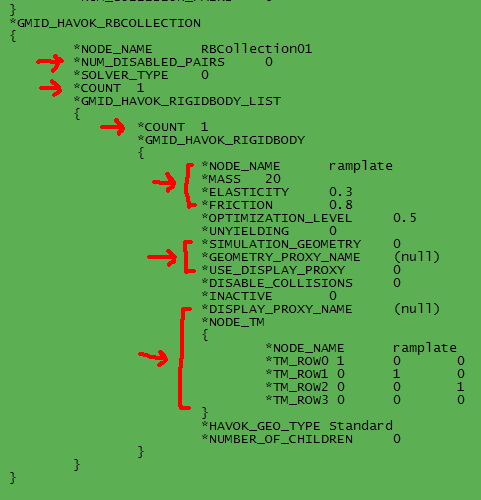
  • RBCollections: This section is found at the very end of the .gmf and wraps everything up.

    • NUM_DISABLED_PAIRS tells how many DIS_COLLISION_PAIRs there are. DIS_COLLISION_PAIRs are used in multi-part objects to tell the game to ignore when the object collides with itself.
    • COUNT tells the computer how many objects (or RIGIDBODYs) are in the RBCollection. Once again, there are two of them which must be the same.
    • NODE_NAME tells the computer which mesh this object uses. It must be the same NODE_NAME used in the mesh. And guess what? There's two of them again!
    • MASS determines how heavy this component is. This will be the default mass used if no mass is specified in the .txt file.
    • ELASTICITY determines how elastic this component is. A high number means it is very elastic (will bounce when it hits something) and a low number means it is very rigid (will just stop when it hits something).
    • FRICTION determines the friction of this component. A high number means it will slow down and stop very quickly when it moves, and a low number means it will tend to keep sliding.
    • UNYIELDING determines whether or not this object can move. 0 means movable, 1 means it won't budge no matter what.
    • SIMULATION_GEOMETRY is a number that depends on the component's collision. If the component has separate 'collision mesh' (which the ram plate doesn't) SIMULATION_GEOMETRY must be set to 3. If not, then it will be 0 or 2. You will only need to change it if you add or remove stuff.
    • GEOMETRY_PROXY_NAME is the name of the collision mesh of this component. If there is none, it is set to (null). This is the name that must be used for the 'passthru' parameter in the .txt file, or the NODE_NAME if there is no geometry proxy.
    • USE_DISPLAY_PROXY and DISPLAY_PROXY_NAME deal with display proxies, which is just like a geometry proxy except the other way around. You probably won't have to deal with this.
    • DISABLE_COLLISIONS determines whether or not this object can collide. 0 means it does, 1 means it passes through stuff.
    • NODE_TM determines which way the mesh faces and where it is relative to 0,0,0. The TM_ROWs here are just like the ones used for connection points.

Reskinning Components

Making copies of components with different skins is the simplest form of modding you can do. Let's say you want to make a 'force field' component. It would be shaped like a ram plate, except it would have an energized look and be semitransparent. Here's how you would do it:

  1. Make a copy of the ramplate folder in your Components folder and rename it to something like 'forcefield'.
  2. Decompile ramplate1.gmf in the folder.
  3. Open the decompiled .gmf in Notepad. Find the BITMAP line in the materials list - it should be set to 'ramp_plate.bmp'. Change the file name to something else, like 'force_field.bmp'. Why do you have to do all this gmf editing? Why can't you just copy the folder and edit the other ramp_plate.bmp? Because if there are two textures with the same name, they will get mixed up between the two components that use that name, even if the textures are in different folders.
  4. To make the component semitransparent, find the MATERIAL_TRANSPARENCY line and set it to 0.5. If you didn't want the component semitransparent, you would leave this blank.
  5. Recompile the .gmf. It is not necessary to rename it to something other than ramplate1, but doing so might be useful to avoid confusion with the other ramplate1.
  6. Open ramp_plate.bmp in the 'maps' folder. It should be a black background with the sides of a ram plate on it. This step is exactly like skinning a bot: just use Paint Shop Pro, Photoshop, or whatever program you may have to put a nice force field texture over the ram plate texture. Save the file, and be sure to rename it to whatever you renamed it to in the gmf. Otherwise the component will appear all white.
  7. Make a .txt file for your new component, being sure to use the dir and model name of your new component and not of the ram plate.

And that's it! Now a force field component should appear in your game. That wasn't very hard, was it? You can do the exact same steps to reskin any other component too, not just the ram plate. Keep in mind, however that you can't apply a texture to components without TVERTS and TFACES in the mesh. If you try, it will just be a garbled mess (but a very cool looking animated mess if you do it right).

Making and Editing Attachment Points

You'll probably notice that the force field can still only attach to extenders, and can only be attached by its face. Suppose you wanted to attach it by its edge, and you wanted it to attach to the baseplate like a motor. Or perhaps you want to be able to stack force fields one on top of the other. To do this you'll need to do a little attachment point manipulating. This is almost as easy as reskinning. You'll only need to do a bit of editing in a small section of the gmf. Here's a step-by-step walkthrough of what you would do:

  1. Find the attachment point in the decompiled .gmf, specifically the line that says 'Attach = Generic_F, Generic_M'. To make the ram plate able to attach directly to the chassis, add Base_F to the list.
  2. To make another connection point, first highlight the ENTIRE attachment point like this:


    Copy and paste this directly below the last line of what you just highlighted (directly above *GEOMOBJECT). Do not paste it into the middle of something! The brackets around all the stuff in the .gmf must always line up vertically (or in other words, there must be a { for every }). If they don't, the .gmf won't compile properly.
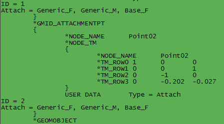
  3. Rename the connection point 'Point02' and change its ID to 2.
  4. Now comes the tricky part. In order to make the new attachment point be on the edge of the ram plate, you must edit the TM_ROWs. Remember that TM_ROWs 0-2 determine direction and TM_ROW 3 determines position. In this case, the correct numbers for TM_ROWs 0-2 for an attachment point on the bottom edge happen to be 100|001|0-10. You have no way of knowing this; normally you would guess between the cardinal directions mentioned earlier. In order to determine TM_ROW 3, you need to look at the mesh vertexes. Notice that many of the numbers are the same. By imagining a ram plate, you can determine that the numbers in the first column are the ram plate's width (because they are the biggest), the numbers in the second column are the height (because they are big, but not as big as width), and the numbers in the third column are the thickness (because they are small). So to put the attachment point on the bottom edge, set the second column in TM_ROW 3 to -0.202. Leave the first column at 0, and set the third column to -0.027 (approximately half the thickness, this centers the point) if you want. This might be confusing at first, so here's a picture of what it should look like.


  5. Look near the top of the .gmf for the object count. Change it from 4 to 5, since you added an object to the file. If you don't do this the .gmf won't compile properly.

That should do it. The force field should now have an additional attachment point on the bottom edge, and it should be able to attach directly to your bot's chassis. You can make as many connection points as you want on a component and give them as many attaching properties as you want. You can also make them face any direction you want if you're smart enough to figure out the TM_ROWs. Just remember to add 1 to the object count for every additional point you put in.

Editing the Mesh

This is the moment you've all been waiting for: actually making new components, not just reskinned or slightly altered previous components. It is possible to make a completely new .gmf from scratch, but it is MUCH easier just to edit the mesh of an existing one. By simply moving the mesh vertexes around, you can make an infinite number of different shapes.

Let's say you're bored with the force field and you want to turn it into a weapon. An energy blade type thing. Doing this isn't as hard as you might think! Here's some more step-by-step instructions:

  1. Find the mesh vertexes in the decompiled .gmf.
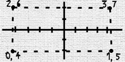
  2. In order to move the vertexes without messing up the component, you need to understand them. If you did the attachment point tutorial, you'll already know that the first column of numbers is the width (x), the second column is the height (y), and the third column is the thickness (z) based on the numbers' magnitude and the shape of the ram plate. The next step is to understand which vertex is which corner of the ramplate. This is important because if you mix up the corners, the mesh faces will get all messed up and you will need to do a lot more work to make it look right than what is necessary. I have found it is often very helpful to draw the vertexes on graph paper. Ignore one of the dimensions, usually thickness (for simplicity), which is in this case z, and then plot x and y. Your drawing should look something like this:


    Notice that vertex 0 is in the same spot as 4, also 1 and 5, 2 and 6, etc. Now if you look at the z dimension again, you can see that vertexes 0-3 are the bottom plane of the ram plate, and vertexes 4-7 are the top plane. This will be important later.
  3. To make an energy blade weapon, we don't want the component to look like a ram plate. We want it to look longer, sharper, and fiercer. Something like this:


    You can probably guess what you need to do next. Change the x and y coordinates of the ram plate to the x and y coordinates of this energy blade we've sketched out. So mesh vertex 0 will have coordinates of -0.6, -0.15, 0; mesh vertex 1 will have coordinates of 0.8, -0.15, 0; etc. Remember not to mix up the corners! For example, don't give mesh vertex 1 coordinates of -0.8, 0.2, -0.055, even though this is a corner of the new model. Those coordinates belong to vertex 6.
  4. Now we'll just add a little finishing touch. We'll make the top plane of the blade smaller than the bottom plane so it has sharp edges, very similar to how you make a wedge when you're building a bot. The vertexes we need to change to do this are 5 and 6. Let's give 5 coordinates of 0.7, 0, -0.055 and 6 coordinates of -0.7, 0, -0.055. That should make a nice, mean-looking cutting edge on the blade. In case you didn't follow all that, this is what the finished mesh should look like:

  5. Go to the attachment points and add Axle_F as an Attach qualifier. This will enable you to put the blade on motors. Also, you should change the y position of Point02 to -0.15 instead of -0.202 to accomodate for the component's new height. If you don't do this the attachment point will be floating in space - not a serious error, but rather unrealistic if you use that point.
  6. Compile the .gmf. If you want the blade to be a weapon instead of just an armor plate (and of course you do) you will also need to edit the .txt file.

Congratulations! You've just turned a basic, boring, everyday ram plate into a really cool energy blade using only Notepad and Dummy's GMF compiler! If you did everything right, the finished product should look something like this (but most likely with a different skin):


It's a tad on the small side right now, but that can easily be fixed, right? Just move the vertexes out farther, or you can just multiply all the numbers by 2 to make it twice as big and with the same dimensions. Once you are comfortable with the ram plate, you can make even more shapes from components with more vertexes, such as the round extender. With practice, you might someday be able to move up to making motors, wheels, and even arenas! The possibilities are endless with mesh editing.

Troubleshooting

Honestly, there are a lot of things that can go wrong when editing .gmf's and it can sometimes be hard to find the problem if it doesn't work. I've listed a few of the most common causes for crashing below.

Those are the most common things, but there are a plethora of other errors that can make your .gmf not work. One effective thing you can try is to undo whatever the most recent change you made was. This lets you know exactly what is causing the .gmf to not work and you can more easily figure out what you're doing wrong. I rarely make more than one change to a .gmf at a time: this makes it easy to know what's wrong if my component crashes. Then I figure out how to make it work.

That's it for now. Later on I'll probably add some more advanced tutorials, but for now you'll just have to settle for the basic stuff and figure out the rest on your own. However, the advanced stuff is much easier to grasp if you understand basic things like mesh and attachment points. Hope this tutorial helped, and happy modding!